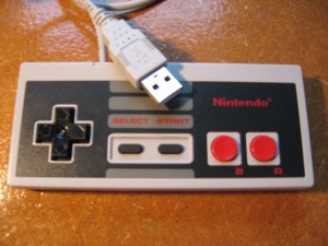
This is mainly a show and tell post. What we have here is a NES controller that has been converted into a USB HID device. This means it can be connected to a computer without installing any drivers (Linux, Mac OS X, and Windows XP).
The circuit, PCB design, and firmware for the Atmega8 micro-controller are courtesy of Raphaël Assénat. His website is a veritable cornucopia of awesome circuitry. And the best part? All of his work is fully documented and provided for use under the GPL license where applicable.
Now the show part is over, time for the tell.
PCB Fabrication
First I would like to say I am no electrical engineer. I love building circuits and playing with micro-controllers but I have very little knowledge of the theory behind a circuit. That said, I learned a few things during this project that I would like to share.
The first lesson: surface mount PCB’s are painful! The actual soldering isn’t so bad. Search YouTube for surface mount soldering and you will get a ton of great instructional videos.
The real issue for me was fabricating the PCB. I usually use the photo fabrication method but one of the tiny traces would get burned off every time. It’s poossible through some trial and error with expossure time I might have been able to get this to work but each failure is expensive! Pre-sensitized copper clad can cost up to $10 per sheet (aprox. 6x6 inches).
I ended up using the toner transfer method which I found tedious at best. I had to experiment several times over with different laser printers, print settings, iron temperature, iron pressure, and ironing time. Too many variables! That said, failures are cheep. If the artwork did not stick to the copper correctly, just clean the copper and try again.
Atmega8 Micro-controller
I actually built this circuit a few months ago. After assembling the circuit and connecting the ICSP programmer I successfully:
- flashed the firmware
- burned the fuses
Then I connected the USB cable to the computer but the device failed to register! I was so frustrated that after all of that work, I just stuck the project on the shelf and forgot about it.
Recently I was working with another Atmega8 based board when I realized my error. See, when you receive your AVR chip from the factory it is configured to use an internal oscilator. This internal osilator circuit tells the AVR what speed to run at (eg: 1 MHz).
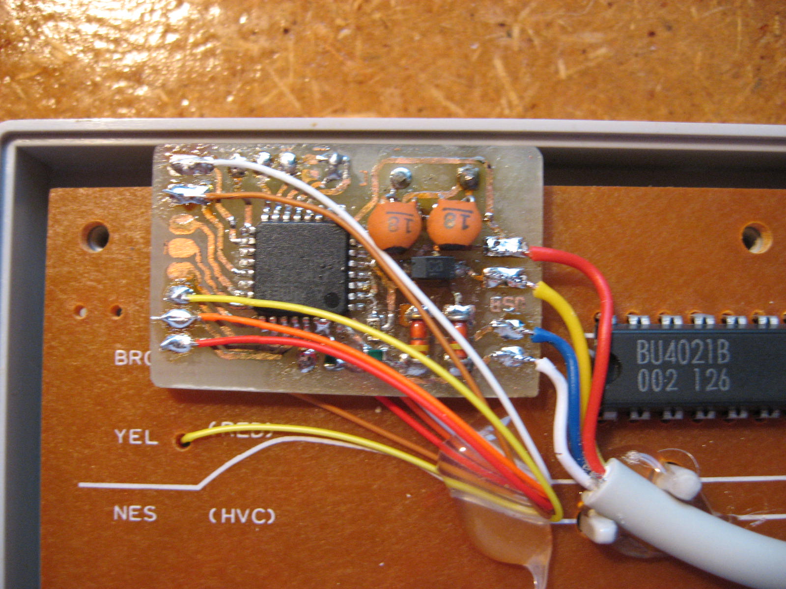
The fuses are a set of bytes in the flash that determine how the chip operates. One of the fuse settings tell the chip to ignore the internal osilator circuit and look for an external one. The NES USB board is an example of a circuit that uses an external oscilator in the form of a crystal.
Beside the crystal are two capacitors and here is where I went wrong. These capacitors are 27pF on Raphaël’s circuit but I used a through hole crystal instead of the surface mount variety and these capacitor values are specific to the crystal! You can find the appropriate values in the crystals datasheet, in my case 18pF.
This explains why I was able to flash the firmware and the fuses. Once the fuses where flashed the AVR chip expected to have a working external oscilator but due to incorrect capacitors the external oscilator couldn’t function and neither could the chip. After replacing the capacitors the circuit sprang to life.
So in closing I hope this helps another noob like me out there.
Comment submitted